PiDAR
This is a system utilizing Raspberry Pi and LIDAR, to be mounted on a drone.
This project is maintained by joedvorak
PiDAR
This repository is an updated version of this BAE 305 project which incorporates changes made to enable easier sampling during flights. The original BAE 305 project can be found at DiontreBaker/PiDAR or in the BAE-305-Project Branch of this repository.
Group Members: Eric Vanzant (Project Owner), Tre Baker (Scrum Master), Kimberly Stenho, Rueben Golyatov, Handerson Coq, Makua Vin
Summary
In agriculture, we as engineers combine science and machines to help us use our environment more efficiently. At the University of Kentucky, engineering students are creating new inventive ways to help farmers and environmentalist alike. This semester our group has taken on the task of creating a platform for wireless control of a LIDAR scanner mounted on a UAV for measuring alfalfa plant height. A LIDAR stands for Light Detection and Ranging. This device sends pulses out to measure light frequencies so that the LIDAR can pick up differences in height on the ground. The first part of the project is to create a mount for the LIDAR so that it will be secure to the drone. Another part of the project is to develop a code for the LIDAR to measure the required data.
Project Features
Goal: Operate LIDAR sampling (both collection of measurements and recording of data) using the 5V R/C Servo-style PWM signals from a UAS flight controller.
To use the LIDAR system, we needed a method to trigger sampling (both taking measurement and recording data) during flights. While some LIDARs can be managed through a simple microcontroller, we have had better results interfacing with computers. We have used the Rasberry Pi in this project for its small size and low weight along with its robust customizability. The LIDAR unit is connected directly to the Raspberry Pi, which controls its operation and records the data. We send signals to the Raspberry Pi using the interfaces built into the Unmanned Aerial System (UAS). As with most UAS, the A3 flight controller installed on our S1000 provides output signals in the form of 5V R/C Servo-style PWM signals. The Raspberry Pi does not a have a simple method of accurately timing these pulses at the necessary resolution so an Arduino microcontroller is used for that purpose. The selected Arduino Shield/Pi HAT incorporates the 3.3V to 5V level shifters and an Arduino Leonardo in one small package.
Finally, it should be possible to control the LIDAR using the standard camera shutter controls on the UAS, but the DJI A3 and Lightbridge has those signals unavailable unless a channel expansion is added to the R/C controller. This text will not describe the setup of the DJI specific hardware like the Lightbridge2 or the channel expander. These systems seem to be in constant flux, but any UAS should be capable of sending an R/C pulse to control auxialry equipment. This description will focus on handling the input signals and recording LIDAR measurements.
PiDAR Project Video
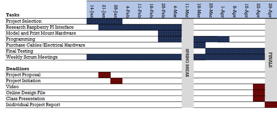
Timeline
Materials
- Raspberry Pi 3
- Micro SD Card
- Arduino Shield for Raspberry Pi B+/2B/3B (DFRobot P/N: DFR0327)
- Scanse Sweep Scanner (LiDAR)
- Spreading Wings S1000 (UAV)
- DJI A3 flight controller
- DJI LightBridge2
- DJI Matrice 600 Series Remote Controller Channel Expansion Kit
- Mounting Bracket (Drawing Provided)
- Panhead Machine Screws (4, M2.5x0.45 mm)
- Micro USB to USB Cable
- 5V Power Converter
- Power Cables
Assembly Procedures
Setting up the Raspberry Pi
- Download the Scanse Sweep SDK.
- Install libsweep.so and SweepPy following the instructions in the download package.
- On the Raspberry Pi create a directory to store the programs at /home/pi/code/sweep
- Place the input_monitor.py and record_scan.py files from the RPi files directory of this repository in the /home/pi/code/sweep directory on the Raspberry Pi.
- Modify rc.local at /etc/rc.local by adding the following line to the end of the file (but before the exit 0 line). An example rc.local file is included, but it is suggested to just add this line to your Pi.
su pi -c 'python3 /home/pi/code/sweep/input_monitor.py &' - Restart the Pi. It will now trigger a scan every time it receives input on pin 4 of the GPIO. The scans are saved in /home/pi/lidarData
- Use the real time clock (RTC) embedded in the Shield/HAT to allow the Raspberry Pi to keep time even when disconnected from the Internet. After inserting a battery in the Shield follow the directions from Adafruit
Description of the Raspberry Pi setup
The Scanse Sweep library provides functions to easily interact with the Sweep once installed. Using SweepPy provides access for the python program, “record_scan.py.” During boot, rc.local is executed which starts a simple python program, input_monitor.py, that sets up a trigger for record_scan.py when there is a transition to a high state on pin 4. It uses an excessively long 2 second debounce time to ensure the recording program is not called too often. The record_scan.py program opens the connection to the LIDAR. It starts scanning. When the fifth scan has been taken, it processes the scan data. It takes all the measurements in the fifth scan and converts them to “angle (in degrees), distance (in cm), x (in cm), y (in cm)” in a cvs format. Python resouce management takes care of closing the LIDAR connection when the Sweep block ends. Finally, the data file is closed.
Setting up the Arduino
- Send the ServoSigTiming.ino program in the Arduino directory of this repository to the Arduino Leonardo on the DFRobot DFR0327 using the IDE of your choice.
Description of the Arduino Program
This simple program just monitors the pulse widths recieved on pin 7 (R/C servo signal input) and toggles pin 4 to a constant high or low state. The pulse threshold for switching from a high to low state has been set at 1515 ms. Although 1500 ms is technically the center point of the R/C servo signal, using 1515 ms provides an offset to avoid excess transitions when the signal happens to be sitting at neutral.
Constructing the mount
The CAD files for printing a mount are in the LIDAR Mount directory of this repository. The mount can be attached to the standard camera support rails on the S1000. Modifications may need to be made for other UAS. Print the parts and assemble as shown in the CAD assembly file.Place the Raspberry Pi onto its provided space in the bracket. Secure the LiDAR to its place in the same bracket, with the machine screws. Attach the USB cable from the Raspberry Pi to the LiDAR. Connect the power cables to the drone’s battery. Attach the power converter to the power cables. Bolt the mount onto the drone.
Miscellaneous electrical components and connections
A converter is necessary to take the 22V power from the 6S LiPo battery to 5V necessary for the powering the Raspberry Pi and Arduino. The 5V power and grounds from the converter can be attached to any of the common 5V and GND pins on the Ardiuno Shield/HAT. A standard servo connection can be used to carry the R/C servo signal from the flight controller output pin (setup as necessary for your UAS) to pin 7 on the Arduino Shield/HAT. Although the standard servo connection has 3 pins, only the signal wire and ground are necessary. A jumper wire must be run from Arduino pin 4 to pin G4 for the Raspberry Pi on the Shield/HAT to carry the signal from the Arduino to the Raspberry Pi through the level shifters built into the Shield/HAT.
Drawings
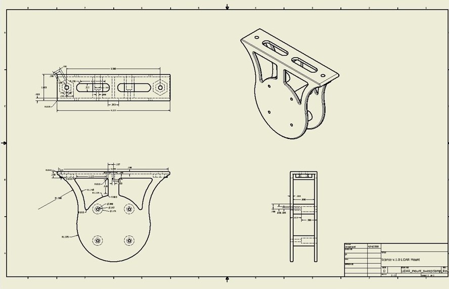 Download LiDAR mount file (.pdf)
Download LiDAR mount parts and drawings (.zip)
Test Equipment
- Complete assembly (componenets listed in the “Materials” secion)
- Monitor
- Keyboard and mouse
- 22V battery
Test Procedure
Operate the UAS to send the necessary R/C signal out. After operation, the data can be downloaded by connectin a keyboard, mouse and monitor to the Raspberry Pi. Navigate to /home/pi/lidarData. The data files are sequentally number. Note, unless a battery has been installed in the Raspberry Pi for the RTC, the time stamps are likely incorrect unless an Internet connection was available while flying for the Raspberry Pi’s time server to initialize to the correct time.
Test Results
Below is a sample of the data collected and stored on the SD card after a successful trial.
    angle, distance, x, y

 263.687500, 2.050000, -0.225400, -2.037571
 266.062500, 2.020000, -0.138710, -2.015232
 268.625000, 1.980000, -0.047512, -1.979430
 271.187500, 1.950000, 0.040412, -1.949581
 273.750000, 1.930000, 0.126228, -1.925868
 276.125000, 1.910000, 0.203793, -1.899097
 278.687500, 1.890000, 0.285475, -1.868316
 281.250000, 1.870000, 0.364819, -1.834068
 283.812500, 1.860000, 0.444066, -1.806213
 286.562500, 1.870000, 0.533064, -1.792412
 288.750000, 1.850000, 0.594663, -1.751821
 291.000000, 1.830000, 0.655813, -1.708452
 293.562500, 1.850000, 0.739536, -1.695755
 296.125000, 1.840000, 0.810209, -1.652017
 298.687500, 1.860000, 0.892860, -1.631687
 301.375000, 1.880000, 0.978798, -1.605103
 303.937500, 1.900000, 1.060748, -1.576329
 316.750000, 0.010000, 0.007284, -0.006852
 329.562500, 0.090000, 0.077596, -0.045594
 342.375000, 0.150000, 0.142959, -0.045418
 351.937500, 0.190000, 0.188122, -0.026648
 ...
Design
Design considerations for the physical, 3-D printed mount and assembly include:
- Minimum mount thickness: 0.1 in.
- Additional material added to base considering stress points
- Depressions for hex nuts to maintain consistency with exisitng mount components
- Neat and compact storage of components and wiring to prevent interference during flight